Professionals in any discipline need a common language to convey messages and exchange ideas. This language may be in verbal, written, and/or visual form. Engineers, for example, use technical drawings to describe a product or a component. The purpose of these drawings is to convey all information necessary to fully describe a product structure so that it can be built. Engineering drawings use standardized methods and symbols that makes understanding the drawings simple with little or no ambiguity.
In many cases, a single drawing is not enough to convey all information. Architects use multiple elevation and cross section drawings to describe a building. They may use different line thickness and styles to convey additional information. These drawings, or blueprints, are well understood by others who many be involved in the construction of the building, including regulatory bodies.
Unfortunately, none of the above is true in the field of networks (TCP/IP-based networks, to be specific). The profession lacks a standard or common convention that defines how a network is supposed to be documented visually or by any other means. The practitioners are free to present the network in any fashion and use any set of symbols for network components. In fact, drawing conventions and symbols used today are often determined by the drawing software or by vendor-supplied icons.


Consider, for example, the above network drawings. These are likely meant to be used as pictorial representation of networks. Yet, it is common to see many similar diagrams used for network documentation with few extra details, such as IP addresses, device models and/or port numbers.
This lack of common drawing conventions and symbols has several drawbacks, including:
- Inability to document certain aspect of networks such as abstractions and virtualization
- Inability to communicate network details among Professionals
- Misinterpretation of the documented information
- Loss of information that is not explicitly including in the diagram.
For all of these reasons, I want to argue that:
- There should be a common set of conventions to communicate network information among professional. If drawings are used, they should communicate sufficient details between, say, designers and builders, or between network administrators and support staff. These diagrams should be sufficiently accurate to be used as single source of truth document for a network.
- One visual representation is not sufficient to convey all details about a network: The common way to document networks focuses on the physical topology of the network. This type of drawings usually includes the network components and the links among them (see above diagrams). I use the term Physical loosely because the links are actually a representation of the layer 2 (Data Link) topology (e.g. Ethernet or Wi-Fi connections) rather than a true representation of the physical infrastructure of the network.
To explain the significance of using proper and common network documentation and symbols, consider the following set of drawings:
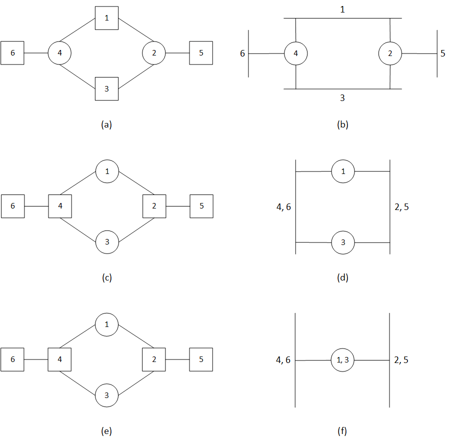
The drawings in the left column show connectivity between six devices at Layer 2, while the right column shows the corresponding Layer 3 topologies. The circles represent routers (forwarding packets at layer 3) and the squares represent switches (forwarding packets at layer 2). The drawings show that:
- Using known and common symbols is important to interpret the network correctly. Figure (b) shows three L2 segments separated by two routers, while drawing (d) shows an entirely different topology when the same devices change positions.
- Network layer-3 information is not shown explicitly the diagram but can be inferred by the location of the devices and the reader’s knowledge of the functions of these devices. In this case, drawing (f) shows the topology when routers 1 and 3 implement VRRP.
The above is a long argument to make a point: a physical topology drawing is not sufficient to describe a network without identifying the function of each device. Furthermore, the drawings do not show any abstractions, such as VLANs, that can change the layer 3 topology significantly.
Referring to the same set of drawings, you can notice that if the designer hands over the drawings to a builder, it will be up to the latter to determine what interfaces are used to connect devices, which IP addresses to be used, etc. If the designer need to control these details, they have to either clutter the drawing, or use other set of documentations.
I do not have a solution to the documentation challenge. When I practiced network design, I used many drawings to present different aspects of the network designs, and I used these drawings to communicate with colleagues, contractors, and customers. The following drawing shows my favorite way to document a network to be ready for construction.

My intention is to move away from mere pictorial representation of the network to more precise documentation that can be used for construction. The pictorial representation is still useful, of course, to communicate with non-technical personnel or visualize the network at high level.
To be continued…