Z-Wave is a wireless communications protocol that uses low-energy radio signals operating in the ISM band and support mesh networking topology. Z-Wave is used primarily for home automation for wireless control of home appliances e.g. lighting, security systems, thermostats, garage door openers etc.
Z-wave protocol is developed by Sigma Designs, Inc. including encryption. Open-Zwave, an open source implementation of Z-Wave, is available but it does not support a security layer. Z-wave PHY and MAC layer specifications are defined in ITU-T G.9959 standard.
The following table lists the basic features of z-wave technology:
| Specification | z-wave support |
|---|---|
| Standard | ITU-T G.9959 (PHY and MAC) |
| RF Frequency Range | 868.42 MHz in Europe, 908.42 MHz in US |
| Data rate | 9.6, 40, 100 Kbps |
| Maximum Nodes | 232 |
| Architecture | Master and slave in mesh mode |
| MAC layer | CSMA/CA |
| RF PHY modulation | FSK (for 9.6kbps and 40 kbps), GFSK with BT=0.6 (for 100 kbps) |
| Coding | Manchester(for 9.6kbps), NRZ(for 40 and 100 kbps) |
| Distance | 30 meter in indoors, 100 meters in outdoors |
Find Z-Wave Specifications Here/
Z-Wave Network
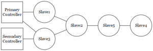
A z-wave network consists of controllers (one primary controller and zero or more secondary controllers) and slaves. Controller devices are the nodes in a z-wave network which initiates control commands. The slave devices are the nodes which replies based on command received and also execute the commands.
Controllers and slave nodes also forward the commands to other nodes in the network. This enable the controller to establish communication with nodes that are not with its radio frequency range.
Z-Wave Network
Controllers
All Z-Wave networks require a controller. The first controller on the network is the primary controller and is responsible for including and excluding nodes, assigning node IDs to nodes and maintaining a network routing table. A controller is assigned a factory Network Id which it assign to all nodes that are included on the network.
Controllers which are added to the z-wave network using the primary controller are known as secondary controllers. They do not have capability to include or exclude any nodes. They will get copies of the routing tables from primary controller.
A USB controller stick that you plug into a computer is a common type of controller.
Slaves
The slave devices/nodes in z-wave network receive the commands and performs action based on the commands. The slave nodes are unable to transmit information directly to other slave nodes or controllers unless they are instructed to do so in the commands. The slave nodes do not compute routing tables, but they can store routing tables.
Examples of slave nodes include lights, switches etc. Nodes can be mains powered or battery. Mains powered nodes (always on) can be used as repeaters.
Home ID
The z-wave protocol uses Home ID field to identify individual networks. The Home ID is 32 bit unique identifier which is pre-programmed in all the controller devices. At the start, all slave nodes will have Home ID value of zero. Once included in the network, they are assigned the Home ID by the controller. Controllers exchange Home ID which makes it possible for more than one controller to control slave nodes.
Node ID
A node ID is 8 bit value. This ID is also assigned to slave nodes by the controller. Node ID’s are used in order to address individual nodes in a z-wave network. These Node ID’s are unique within a network defined by a unique Home ID.
Mesh Topology
A mesh topology allows any node to connect to any other node using multiple connections. In Z-Wave, a packet can hop over 4 nodes, which effectively limits the maximum distance between a controller and the farthest node. To act as a forwarding node the node must be mains powered. Battery powered nodes cannot forward packets.
Z-wave protocol stack
The z-wave protocol main function is to communicate very short messages of few bytes long from a control unit to one or more z-wave nodes. It is a low bandwidth and half duplex protocol to establish reliable wireless communication. The z-wave protocol does not need to deal with time critical or streaming data.

Z-Wave Protocol Stack
As shown in the figure, z-wave protocol stack consists of 5 layers: PHY layer, MAC layer, Transport layer, network layer and application layer. The security layer is not defined in z-wave open protocol specifications and hence it is implementation specific. Here are the major functions of these protocol layers:
- Physical layer handles modulation and RF channel assignment as well as preamble addition and synchronization at the transmitter or the receiver, respectively.
- MAC layer manages HomeID and NodeID and controls the medium between nodes using collision avoidance and backoff algorithms.
- Transport layer handles the transmission/retransmission and reception of frames, and acknowledgements as well as insertion of checksum.
- Network layer is responsible for frame routing, topology scan and routing table updates.
- Application layer handles payloads in the transmitted/received frames.
Physical layer
As z-wave frame at the PHY layer consists of a preamble, SOF(Start of Frame), Frame data and EOF(End of Frame) symbol. The data is either Manchester coded or NRZ coded based on data rate. This layer inserts the preamble, performs the modulation/demodulation and RF channel selection before frame transmission and reception.
The frequency bands, data rate and channel bandwidth supported by z-wave technology in Canada/USA are:
- RF Center Frequency: 916.00, 908.40MHz
- Data Rate: 100/40/9.6Kbps
- Channel Width: 400/300/300KHz
Security
As z-wave open protocol architecture does not specify security layer specifications it is implementation specific. z-wave security layer provides secured communication between nodes as well as between controllers and nodes.
MAC Layer
The MAC layer handles medium access control among slave nodes based on collision avoidance and backoff algorithms. It also responsible for network operations based on HomeID, NodeID and other parameters in the z-wave frame.
Transport Layer
The Z-Wave transport layer is mainly responsible for retransmission, packet acknowledgment, waking up low power network nodes and packet origin authentication. The z-wave transport layer (or transfer layer) consists of four basic frame types. These are used for transferring commands in the network. All frames use the following format:
Transport Frame
Singlecast frames:
This type of frames is transmitted to one specific z-wave node. The frame is acknowledged so that transmitter will know whether the frame is received or not. If this frame or its ACK is lost or damaged then the singlecast frame is retransmitted.
ACK frame:
It is singlecast frame that is used for acknowledgment. The frame does not include data payload.
Multicast frame:
This frame is transmitted to more than one node (up to 232 nodes). This type of frame is not acknowledged; therefore, it is not used for reliable communication.
Broadcast frame:
This frame is sent to all the nodes in a network and it is not acknowledged by any node.
Network Layer
The z-wave network layer controls the frame routing from one node to another. Both controllers and slave nodes participate in frame routing. The network layer is responsible for the following tasks:
- Transmission of a frame with correct repeater list
- Scanning of network topology
- Maintenance of routing table in the controller
The network layer includes two kinds of frames. These are used when repetition of frames become necessary.
Routed Singlecast Frame:
It is a one node destination frame with acknowledgement which contains repeater information. The frame is repeated from one repeater to another until it reaches the desired destination.
Routed Acknowledge Frame:
This acknowledgement frame is a routed singlecast frame without payload. This will inform the controller that the routed singlecast frame has reached the desired destination.
The controller maintains the routing table that contains information about all the nodes in the network. The routing table is a bit field table as shown in the following table. The routing table is built by the primary controller based on information received from all the nodes in the z-wave network.
| 1 | 2 | 3 | 4 | 5 | 6 | |
|---|---|---|---|---|---|---|
| 1 | 0 | 1 | 1 | 0 | 0 | 0 |
| 2 | 1 | 0 | 0 | 0 | 1 | 0 |
| 3 | 1 | 1 | 0 | 0 | 0 | 0 |
| 4 | 0 | 0 | 0 | 0 | 1 | 0 |
| 5 | 0 | 1 | 0 | 1 | 0 | 0 |
| 6 | 0 | 0 | 0 | 0 | 0 | 0 |
Application Layer
This layer is responsible for decoding and executing commands in a z-wave network. The frame used in application layer consists of following fields.
Application Frame
The command class defines these commands:
- 0x00 – 0x1F (This command class reserved for Z-wave protocol)
- 0x20 – 0xFF (This command class reserved for Z-wave application)
All the z-wave frame types except the acknowledgement frame contain an application command.
Messages and Responses
Messages follow a command response format. Generally all messages are sent from the controller to the slave nodes. The node acknowledges the message. Slave nodes cannot initiate messages, so they can only respond. However forwarding nodes can send predetermined messages to assigned (associated) nodes. This type of behavior is useful with devices like motion sensors, light switches etc., which need to send motion data immediately to a controlling device.
Adding Nodes to a Network
To become part of a Z-Wave network a node needs to be included into the network. This can only be done on the primary controller. Before inclusion a slave node has a network ID of 0 and Node ID of 0. After inclusion the node has network ID of the controller and a unique Node ID between 2 and 232.
Note that 8 bits are used for the node ID and the primary controller has the node ID of 1. Some IDs are reserved.
Removing Nodes from a Network
Any Controller can remove a node from a network. When a node is removed it’s network ID and node ID are set to zero.
Neighbour Lists
Each node maintains a list of adjacent nodes that it can communicate with. They communicate this list back to the controller when requested and the controller uses it to build a routing table.
Routing Table
The primary controller creates and maintains the router table. The controller uses this table to route packets across the network using source routing.
Controllers
A Z-Wave network requires at east one controller. This controller is the primary controller. Other controllers can be added to the network and can be used for issuing commands to nodes. Controllers are divided into two types:
- Static Controller are mains powered and should not be moved.
- Portable controllers are usually battery powered and as such cannot route messages. A portable controller can be the primary controller and that is often the case in very small networks.
All controllers have a copy of the routing table.
Wake Up and Polling
During the “wake up” the device exits the status of the so-called “deep sleep” and sends out a specific signal to the Z-Wave controller. This wake up notification tells the controller if it is ready for the change of the configuration information. The device stays awake for some time (this time is individual for each device) to exchange the data with the controller.
The wake up does not occur due to an ordinary function of the device (e.g. when the movement sensor detects some movement). This event forces the device to send out a message into the Z-Wave controller on the change in the status of the device, then the device immediately returns to sleep. This behavior minimizes the power consumption of the device and thus the life of batteries.
Wake UP Interval
Wake up occurs in certain time intervals, set either by default or by the user. The wake up can be started manually by pushing the button or buttons on the device too (individually for each device).
When a device configuration needs to be changed, the request for the change is carried out only when the device is “awake”. For instance, if a change in the sensitivity of the motion sensor is needed, it is necessary to wait for the next wake up. If the wake-up intervals are very long, then it is necessary to carry out a manual wake up.
Polling
A “poll” is a request from the Z-Wave controller to the Z-Wave device to send out information (on their status). Only those devices that are supplied from the mains (not batteries) have the radios switched on all the time so they can respond to this request anytime. A battery powered device cannot receive poling from the Z-Wave controllers while the device is still sleeping (which is most of the time). Each Z-Wave controller can have this feature implemented in a different way but in general there are two options: polling is either held or excluded. Polling interval specifies the time between consecutive “polls” of the devices.
Devices implementing the Z-Wave Plus standard has the so-called “reporting group” by default. This means that the device sends out data into the controller if something interesting happens.
Polling causes heavier traffic in the network and this may cause the delay of communication between the devices and the Z-Wave controller. It depends on the size of the network, the design of the network, the coding and the type of devices.
“polling” and the “wake up” functions do not affect each other. If the device is supplied from batteries, polling cannot be set because the device’s radio is off while it is sleeping. A device that is supplied from the mains, on the other hand, is always switched on and “wake up” is not used.
Useful Links
- http://www.openzwave.com/dev/
- https://hackingathome.wordpress.com/2017/12/30/getting-started-with-z-wave/
- http://openzwave.github.io/python-openzwave/openzwave.html
- https://awesomeopensource.com/project/OpenZWave/open-zwave
- https://docs.smartthings.com/en/latest/device-type-developers-guide/z-wave-primer.html