Contents
Like many people, I have started learning about Software-Defined Networking and OpenFlow using Mininet, which is a great virtual environment to use. However, Mininet has some limitations, and I found myself looking for hardware alternatives.
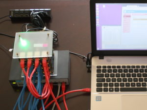
This article describes how to build an OpenFlow lab environment that can be used for learning, research, or application development. The lab consists of four Zodiac-FX switches , a standard 8-port managed switch, and a computer.
OpenFlow Lab
Design Overview
A typical SDN network includes OpenFlow switches, a controller (or more), and the computing nodes that connect to the switches and generate the traffic. A realistic lab environment should provide the ability to create some common network configurations and generate realistic traffic in the network. The low cost of the 4-port Zodic-FX switches offer the opportunity to use multiple of them to create a realistic topology using a reasonable budget.
The nodes needed for the lab, including the server running the controller are created as Linux virtual machines and containers (LXC). Containers behave much like virtual machines, but they include only the software components they need to operate rather than an entire operating system. This improves performance and reduces the memory requirements.
The traffic from the controller and virtual hosts is segregated using VLANs. The VLANs carry traffic from each virtual host to a managed switch. The switch directs the traffic from each VLAN to the ports that connect to the OF switches.
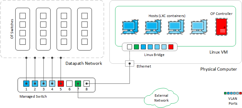
Figure 1: SDN Lab.
Figure 1 illustrates the lab infrastructure to be built. The lab consists of a PC connected to a standard 8-port layer-2 switch. The switch other ports are connected to the OpenFlow switches. Another two ports are used to connect to an external network (the home or school network).
Let’s begin building the lab.
Requirements
Hardware
- A PC (or Mac) with virtualization software to run a Linux VM. The computer must have at least one Ethernet port. You can also use a Linux machine.
- An 8-port managed switch
- OpenFlow switches: Zodiac FX lab pack (4x switches)
- Ethernet cables
- Internet connection (for software installs)
Software
-
- Virtualization software (I use VMware Workstation Player)
- Ubuntu 16.04 Desktop image, to create a Linux VM.
- RYU controller.
- FlowManager, an app I wrote for learning OpenFlow.
- Wireshark, a packet capture app.
- Netcat, a network utility to read and write data using the TCP/IP protocol.
- Curl, command line tool and library for transferring data over many protocols.
- Postman, an HTTP client for testing web services.
- Packeth, a packet generation app.
Switch Configuration
This section deals with configuring the lab’s hardware switches and making the necessary Ethernet cable connections.
Managed Switch
Refer to the managed switch documentation to configure the switch according to the following specifications (use Figure 2 as a reference):
- Create VLANs 10, 20, 30, 40, 80, and 90.
- Port 8 should tag all VLANs.
- Ports 1 to 4 should untag VLANs 10 to 40, respectively.
- Ports 5 and 7 should untag VLANs 80 to 90, respectively.

Figure 2: Managed Switch Configuration
OpenFlow Switches
Refer to the Zodiac-FX User’s Guide to configure the switches as follows:
- Upgrade the firmarware to the latest version.
- Change the default switch IP address (10.0.1.99) to give each switch unique address.
- Disable OpenFlow in one of the switches and assign all ports to VLAN 200 (native) to turn the switch into a standard L2 switch (I’ll explain later).
- Make sure OpenFlow is enabled on the other three switches and that the controller IP address is 10.0.1.8 (this is the default).
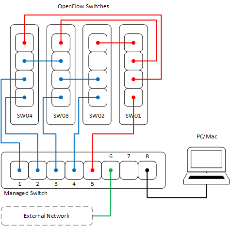
Figure 3: Initial Physical Connections.
Cable Connections
Finally, make all the cable connections as shown in Figure 3. The red links connect the OF controller to the controller ports on the switches while the blue links make up the datapath network topology. The managed switch separates the VLAN-tagged traffic from the virtual hosts on the PC/MAC into physical ports connecting to the corresponding OF switches. The green link connects the PC/MAC to an external network (and the Internet) to be able to download and install the software required for this lab.
Of course, all these connections can be changed at your discretion and according to your lab experiment or research requirements.
Host Computer Setup
If you have a computer running Linux as the primary OS, you can skip to the Linux setup section. I am using a PC running Windows 10, put you probably can use a Mac as well.
Enable VLANs
Some PC NICs strip VLAN headers by default. To enable them, follow this procedure.
I’ve noticed that the default setting is restored after some Windows updates, so you may want to do the above procedure after each update.
Install Linux Virtual Machine
This article does not cover how install the virtualization software and use it to create the Linux VM. Please consult other documentations for this task.
Using a virtualization software, create a Linux VM using the following parameters
- OS: Ubuntu 16 desktop
- CPU cores: 1
- Memory: 2GB
- Hard Disk: 40GB
- Network Adapter: 1 (Bridged to the Ethernet port)
By the end of this installation, the Linux VM should be able to obtain an IP address dynamically from DHCP on the external LAN. Otherwise, check the physical connections to make sure that:
- The physical computer Ethernet port is connected to the managed switch port 8.
- The external LAN is connected to switch port 6
Alternatively, configure a static IP address on your VM to be able to access the external network and the Internet.
Linux (Virtual) Machine Setup
This section deals with installing and configuring VLAN interfaces and Linux containers on the Linux VM (I will just call it VM from now on). The VM will act as a server that hosts the SDN controller. It will have two VLAN interfaces, one that connects to the OF switches and will represent the OF channel, the other will connect to the external network. The containers will be used to generate host traffic and each will have its own VLAN interface.
Note: This will be a good time to download and install Wireshark in the VM to be able to troubleshoot any problem. You can also install Wireshark on the host computer to be able to see all traffic in and out of the VM.
Create a Linux Bridge
The goal of this step is to create a bridge on the VM. The bridge connects all VLAN interfaces that will be created later.
Begin by installing bridge-utils:
$ sudo apt-get update
$ sudo apt-get install bridge-utils
Take note of the name of the Ethernet port on your VM (mine is ens33) and create a bridge br0 (or choose anther name):
$ brctl addbr br0
$ brctl addif br ens33
Edit the file “/etc/network/interfaces” to automatically create the bridge at start-up and connect the physical interface to it.
Note: If DHCP is not enabled, add static IP address configuration to the text below.
auto br0
iface br0 inet dhcp
   bridge_ports ens33
   bridge_stp off
   bridge_fd 0
Restart networking (or reboot the machine):
$ sudo /etc/init.d/networking restart
Verify that the bridge exists and test the connectivity to the external LAN again.
$ brctl show
bridge name  bridge id          STP enabled  interfaces
br0          8000.000c29b27297  no           ens33
Verify also using ifconfig command.
Install Software
While you are connected to External LAN, complete the installation of the software listed in the Requirements section and any other software you may need.
Create VLANs
We need to create two VLAN interfaces on the VM. VLAN 90 will be used to connect with the external network, and VLAN 80 will connect the VM to the OpenFlow network, which links the controller to the switches.
Begin by installing the VLAN module and loading it into the kernel.
$ sudo apt-get install vlan
$ sudo modprobe 8021q
Add VLAN 80 to the existing interface:
$ sudo vconfig add ens33 80
Assign an IP address to the new interface and start it:
$ sudo ip addr add 10.0.1.8/24 dev ens33.80
$ sudo ip link set up ens33.80
Test the connectivity to the OF switches with ping. Now, packets from the VM will be tagged with VLAN 80 in their way to the managed switch and untagged at port 5. You can also use Wireshark to verify that ICMP packets are tagged.
Make the configuration permanent by loading the VLAN module at boot time.
$ sudo su -c 'echo "8021q" >> /etc/modules'
Also, edit the “/etc/network/interface” to include the permanent configuration.
auto ens33.80
iface ens33.80 inet static
    vlan-raw-device ens33
    address 10.0.1.8
    netmask 255.255.255.0
    network 10.0.1.0
    mtu 500
Restart networking (or reboot the VM) and verify the connectivity again before you proceed to the next step
$ sudo /etc/init.d/networking restart
Adding VLAN 90 is not strictly required but it may be needed if you want to segregate the traffic of the VM from the physical host’s.
$ sudo vconfig add ens33 90
Edit the “/etc/network/interface” to assign a static IP address:
auto ens33.90
iface ens33.90 inet static
   vlan-raw-device ens33
   address 192.168.2.120
   netmask 255.255.255.0
   gateway 192.168.2.1/24
   dns-nameservers 8.8.8.8 8.8.4.4
   mtu 1200
Move the cable connected to port 6 on the managed switch to port 7, which untags VLAN, before restarting networking (or rebooting the VM) and verify the connectivity to the new network.
$ sudo /etc/init.d/networking restart
$ ping 192.168.2.1
$ ping 8.8.8.8
You should also see the a routing table similar to the following
$ route
Kernel IP routing table
Destination    Gateway        Genmask          Flags   Metric   Ref   Use  Iface
default        192.168.2.1    0.0.0.0          UG      0        0       0  ens33.90
10.0.1.0       *              255.255.255.0    U       0        0       0  ens33.80
link-local     *              255.255.0.0      U       1000     0       0  ens33.80
192.168.2.0    *              255.255.255.0    U       0        0       0  ens33.90
Notice that all traffic out of the VM will be directed to the external network except OpenFLow traffic between the controller and the OF switches.
Build the Base Container
This section describes how to build a Linux container, connect it to the network, and install the software tools that will be used for the lab. For more information about LXC, see this guide and my previous blog.
Start by installing LXC:
$ sudo apt-get install lxc lxc-templates
First, we want to disable the default bridge “lxcbr0“ that is created as part of LXC installation. Edit file “/etc/default/lxc-net” and change thus line:
USE_LXC_BRIDGE = “false”
Connecting a container to a vlan network allows the network traffic from the container to be tagged with a VLAN ID. Since we will create multiple containers, each of them will have a different VLAN ID to be able to forward its traffic to a separate switch on the managed switch.
Edit the file “/etc/lxc/default.conf” to change the network type:
lxc.network.type = vlan
lxc.network.link = br0
lxc.network.vlan.id = 10
lxc.network.flags = up
lxc.network.mtu = 500
lxc.network.hwaddr = 00:16:3e:xx:xx:xx
Now you can create a container from an Ubuntu template (there are also other templates to choose from):
$ sudo lxc-create -n base_container -t ubuntu
Executing the command for the first time takes a few minutes. Once the container is created, take note of the username and password that are displayed. You will need these to access your container.
Issue the following command to check everything is okay to run containers.
$ sudo lxc-checkconfig
If you start the container now, it will try to get a DHCP address from the network it is connected to and this will delay the boot time. We actually want to (temporarily) connect the container to the external network to download some software, so move the cable connected to the external network to port 1 on the managed switch before you start the container.
Start your new container using the command:
$ sudo lxc-start -n cont_a -F
At this point, we can use the base_container to install the software tools we need then make copies of the container. Note: to use GUI application you will need to modify the configuration file, which is not covered here.
Once inside the container, you can exit using:
ubuntu@base_container:~$sudo poweroff
Replicate the Base Container
Copy the base_container four times using the names host1, host2, host3, and host4:
$ sudo lxc-copy -n base-container -N host1
This will create identical copies of the base_container. You will need to edit the container configuration file “/var/lib/lxc/<container_name>/config” to change the VLAN ID and add static IP address. Each container has to have its own VLAN (10, 20, 30, and 40, respectively). The IP addresses can change based on the topology you intend to build but I recommend assigning all containers IP addresses from the same subnet initially.
Example:
# Network configuration
lxc.network.type = vlan
lxc.network.link = br0
lxc.network.vlan.id = 10
lxc.network.flags = up
lxc.network.hwaddr = 00:16:3e:f4:4b:0a
lxc.network.ipv4 = 192.168.16.1/24
Before you proceed, make sure that all Ethernet cables connected to the managed switch are moved back to the arrangement shown in Figure 1, if you created VLAN 90, or Figure 3 otherwise.
This completes building the lab. The next section will put everything together and start the first lab experiment.
Summary
Let’s recap what we did so far:
- Made sure VLAN tags are not stripped at the physical host’s NIC.
- Installed a Linux VM on the physical host.
- Created a Linux bridge on the VM.
- Installed the software tools needed on the VM (not covered in detail here).
- Created two VLANs on the VM to connect to OF switches and external network.
- Created base container and installed software tools on it.
- Replicated the base containers to create the desired number of hosts for the lab.
If you have followed the steps in this article successfully, you will end up with the network shown in Figure 4.
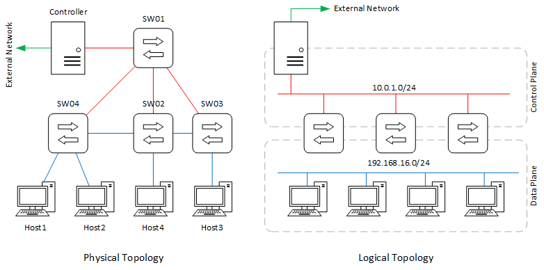
Figure 4: The lab’s physical and logical topologies.
This configuration uses only three OF switches while the fourth, SW01, is dedicated to the control plane. You can change that by using a a bigger managed switch (12+ ports) to connect the controller to the OF switches and use all four of them to build your data plane topology.
Even with only three switches, you can build several practical networks by changing the cable connections between the hosts and the switches and among the switches themselves. Figure 5 shows three different topologies that can be built by changing the roles of the OF switches.
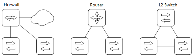
Figure 5: Alternative topology options.
Starting the Lab
This goals of this section are:
- Run the SDN controller and its applications.
- Verify that the OF switch will communicate with the controller correctly.
- The hosts connected to the switches will be able to communicate with each.
Before you begin, run Wireshark to capture and verify the exchange of the OpenFlow messages. Select the Ethernet interface (ens33) to capture and use the filter openflow_v4.
In a new terminal, run the RYU controller, the FlowManager application, and an application that turns the OF switch into L2 switches “simple_switch_13”.
$ ryu-manager --verbose --observe-link flowmanager/flowmanager.py ryu.app.simple_switch_13
You will notice the OpenFlow messages log in the terminal and also in the Wireshark capture shown below:
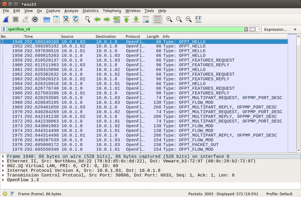
Wireshark screen capture.
Next, start the web browser and enter the url “http://localhost:8080/home/” to access the FlowManager. The application’s home screen shows information about the switches recognized by the controller.
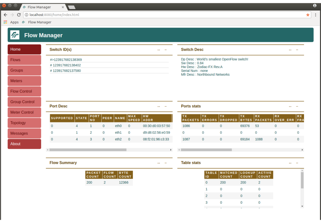
OpenFlow Switch Information.
To start the hosts, you need to start each container in the background:
$ sudo lxc-start -n host1
$ sudo lxc-start -n host2
$ sudo lxc-start -n host3
$ sudo lxc-start -n host4
Generate some traffic between the hosts using ping:
$ sudo lxc-attach -n host1 ping 192.168.16.2
PING 192.168.16.2 (192.168.16.2) 56(84) bytes of data.
64 bytes from 192.168.16.2: icmp_seq=1 ttl=64 time=36.1 ms
64 bytes from 192.168.16.2: icmp_seq=2 ttl=64 time=1.32 ms
64 bytes from 192.168.16.2: icmp_seq=3 ttl=64 time=1.34 ms
^C
--- 192.168.16.2 ping statistics ---
3 packets transmitted, 3 received, 0% packet loss, time 2006ms
rtt min/avg/max/mdev = 1.323/12.954/36.194/16.433 ms
$ sudo lxc-attach -n host1 ping 192.168.16.3
PING 192.168.16.3 (192.168.16.3) 56(84) bytes of data.
64 bytes from 192.168.16.3: icmp_seq=1 ttl=64 time=87.1 ms
64 bytes from 192.168.16.3: icmp_seq=2 ttl=64 time=1.63 ms
64 bytes from 192.168.16.3: icmp_seq=3 ttl=64 time=3.41 ms
^C
--- 192.168.16.3 ping statistics ---
3 packets transmitted, 3 received, 0% packet loss, time 2005ms
rtt min/avg/max/mdev = 1.634/30.734/87.151/39.899 ms
Using a different filter, Wireshark will show the ICMP messages:
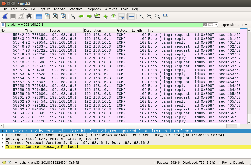
ICMP messages.
Go back to the FlowManager and check the Flows page to see flow entries being created by the simple_switch_13 application to forward hosts’ traffic.
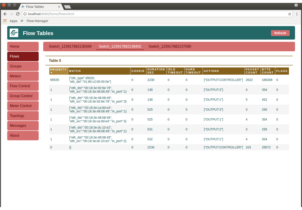
Switch Flow Entries
Finally, go to the Topology page and verify the lab topology:
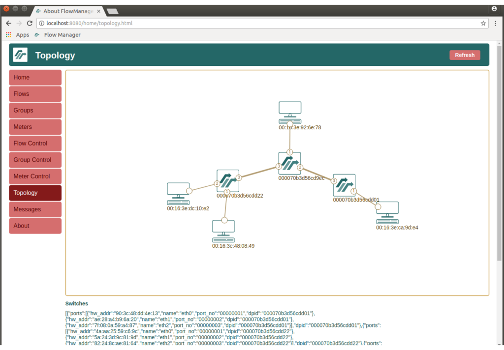
Network Topology
This concludes the lab experiment. Before you power down the VM, shutdown Wireshark and the web browser. Press CTRL-C in the terminal running the controller and stop the host containers:
$ sudo lxc-stop -n host1
$ sudo lxc-stop -n host2
$ sudo lxc-stop -n host3
$ sudo lxc-stop -n host4
I hope you have found this article useful.