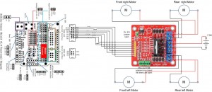
I have created this wiring diagram for the connections between the motor controller, motors, and sensor shield. I’ll update it later to include other components.
And here is an update that includes the servo motor and the range sensor.
And here are the detailed pin assignments for all modules:
| Arduino Pin | Description | Motor Controller | Range Sensor | Servo Motor | Line Detector | Bluetooth Module |
| VCC | VCC | +5V | VCC | Red | V+ | VCC |
| GND | GND | GND | GND | Brown | G | GND |
| D0 | Digital Pin 0 RX | TXD | ||||
| D1 | Digital Pin 1 TX | RXD | ||||
| D2 | Digital Pin 2 | IN4 | ||||
| D3 | Digital Pin 3 (PWM) | ENB | ||||
| D4 | Digital Pin 4 | IN3 | ||||
| D5 | Digital Pin 5 (PWM) | IN2 | ||||
| D6 | Digital Pin 6 (PWM) | ENA | ||||
| D7 | Digital Pin 7 | IN1 | ||||
| D8 | Digital Pin 8 | S | ||||
| D9 | Digital Pin 9 (PWM) | Orange | ||||
| D10 | Digital Pin 10 (PWM) | |||||
| D11 | Digital Pin 11 (PWM) | |||||
| D12 | Digital Pin 12 | Trig | ||||
| D13 | Digital Pin 13 | Echo | ||||
| A0 | Analog input 0 | |||||
| A1 | Analog input 1 | |||||
| A2 | Analog input 2 | |||||
| A3 | Analog input 3 | |||||
| A4 | Analog input 4 | |||||
| A5 | Analog input 5 |
Disclaimer:
The diagrams above are not the only way you can connect the components so use at your own risk.


I have updated the diagram to include the servo motor and the range sensor.
thank you for sensor but i dont understendwhere i needto connect it 🙁
this code from my working car:
//Motor Aint dir1PinA = 7;
int dir2PinA = 5;
int speedPinA = 6;
//motor B
int dir1PinB = 4;
int dir2PinB = 2;
int speedPinB = 3;
unsigned long time;
int speed;
int dir;
void setup ()
{
pinMode (dir1PinA, OUTPUT);
pinMode (dir2PinA, OUTPUT);
pinMode (speedPinA, OUTPUT);
pinMode (dir1PinB, OUTPUT);
pinMode (dir2PinB, OUTPUT);
pinMode (speedPinB, OUTPUT);
time = millis ();
speed = 0;
dir = 1;
}
void loop ()
{
analogWrite (speedPinA, speed);
analogWrite (speedPinB, 555 - speed);
// set direction
if (1 == dir)
{
digitalWrite (dir1PinA , LOW);
digitalWrite (dir2PinA, HIGH);
digitalWrite (dir1PinB, HIGH);
digitalWrite (dir2PinB, LOW);
}
else
{
digitalWrite (dir1PinA, HIGH);
digitalWrite (dir2PinA, LOW);
digitalWrite (dir1PinB, LOW);
digitalWrite (dir2PinB, HIGH);
}
if (millis () - time> 5000)
{
time = millis ();
speed += 20;
if (speed> 555) {speed = 0;}
if (1 == dir)
{dir = 0;}
else
{dir = 1;}
}
}
This post “Arduino robot kit – Range sensor” has some information about the distance sensor. I’ll create a new post soon about controlling the robot with Bluetooth.
Can you make next post about Remote Control or Distance sensor?
Thanks for the scheme, Your job is grate 🙂 i follow you and my car already can move.
Thanks! Have you read the previous posts? I think they have all the details.
Hi, i think your work is great! You are probably the only one on the net showing how to build this kit from dx. I am looking forward to see your complete code. I am having trouble getting the motors to run, so i am looking forward to see have you solved it! Keep the good work up! -Björn