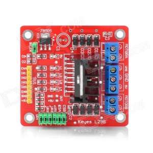
The motor controller module is based on L298N driver. The documentation for the module was hard to find but there are many boards that are based on the same driver. So, I was able to piece the information together and figure out how to use the module.
L298N Controller Module
L298N is a high voltage, high current motor driver chip, with the highest working voltage of 46V, continuous operating current of 2A, and instantaneous peak current up to 3A. The chip contains two “H bridges” which are high-voltage and high current full-bridge drivers that can directly drive two DC motors (or 1 two-phase bipolar stepper motor).
The controller specifications:
- Uses ST’ L298N chip, can directly drive two 3-30V DC motor, and provide a 5V output interface, power for 5V single-chip circuitry, support 3.3VMCU control
- Can easily control the DC motor speed and direction, also control the 2-phase stepper motor
- Driver: L298N Dual H Bridge DC Motor Driver IC
- Driven part of the terminal supply voltage: VMS 5~35V
- Driven part of the peak current Io: 2A per bridge
- The logical part of the terminal supply voltage: 4.5~7V
- The logical part of the operating current range: 0 ~ 36mA
- Control signal input voltage range: 4.5~5.5V (high) / 0V (low)
- Maximum power consumption: 20W
The logic inputs to the controller are:
- ENA and ENB enable the motors A and B, respectively
- IN1 and IN2 control motor A
- IN3 and IN4, control motor B
There are also some jumpers:
- CSA and CSB can be used to sense the motor current if jumpers are removed
- U1-U4 tie inputs IN1-IN4 to 5V and they must be removed to allow full control of the motors
- 5V_EN activates the internal voltage regulator
L298N needs two input voltage: logic voltage and motor voltage. To convert the motor voltage into logic voltage, the motor driver board provides a voltage regulator circuit, which is activated using the jumper 5V_EN. This eliminates the need to supply logic voltage from the Arduino board.
The terminal blocks are:
- MOTORA and MOTORB supply +/- voltage to motors
- VMS supply motor voltage
- 5V supply logic voltage
- GND is the ground
The board has four LEDs to denote the direction of rotation of the motor, and the brightness level is proportional to motor speed. A fifth LED indicates the power status.
The following example specifies control of bridge A using IN1 and IN2 (or N3 and N4) pair:
- To move the motor forward set IN1=H, IN2=L, ENA=H
- To move the motor backwards set IN1=L, IN2=H, ENA=H
- To quickly stop the motor set IN1=L, IN2=L, ENA=H or IN1=H, IN2=H, ENA=H
- To slowly stop the motor (free-run stop): ENA=L (IN1 and IN2 ignored)
Moving the Robot
The first issue that I’ve encountered was the ability to drive four motors with a 2-motor controller. The quick solution was to pair the two motors in each side and control them as one until I can find a way to remove the unnecessary two front motor/wheels. Once that was out of the way, it was a matter of assigning Arduino digital output pins to the motor controller inputs and writing some code.
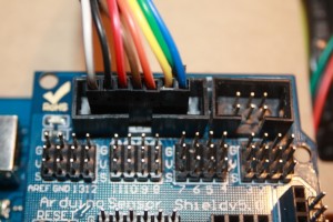
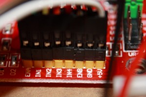
The pins used to connect the Arduino to the L298N board are as follows. To make the wiring nice and tidy, I used the lower pins of the “12864 LCD Parallel Interface” on the Sensor Shield.
Wire colour — Sensor Shield — L298N Controller
White — VCC — +5V
Black — GND — GND
Brown — D3 — ENB
Red — D2 — IN4
Orange — D4 — IN3
Yellow — D5 — IN2
Green — D7 — IN1
Blue — D6 — ENA
And, finally, here is an example sketch to move the robot (I used different pin numbers).


Pingback: Arduino robot kit – Motor library ← Maen Artimy